
Resistive Touch Switch
An assistive switch activated by gentle skin contact.
 Electronics
 Mechanics
 Custom PCB
 3D Printing
 6
6 27
27 0
0 884
884Device Information
Overview
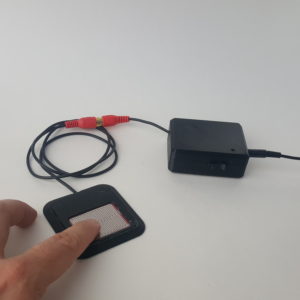
The Resistive Touch Switch is a cost-effective, 3D printable assistive switch that is activated by gentle skin contact. The switch consists of a thin Touch Pad and a Switch Hub. This device can be used to control electronics including phones, computers, adapted toys, and gaming consoles.
The Touch Pad comes in a rectangular or circular shape, and detects contact through skin moisture, similar to how touchscreens work.
How To Use
Setup:
- Position the Touch Pad where the user can access it.
- Connect the Touch Pad to the Resistive Touch Switch Hub using the RCA connector.
- Connect one end of a 3.5 mm male-to-male mono extension cable to the Output jack on the Resistive Touch Switch Hub.
- Connect the other end of the extension cable to the input of the switch-accessible device (e.g., Switch Adapted Toy, USB Switch Hub, etc.).
Usage:
- Turn on the Resistive Touch Switch Hub by sliding the power switch to 'On'.
- Activate the switch by touching the contact portion of the Touch Pad.
Disability Type Description
Users with low hand strength who find assistive switches hard to press may find this device suitable.
Since the contact pad is activated through skin moisture, this switch may not work for users who can't sweat due to a disability (e.g., spinal cord injury) and those with very dry skin.
Estimated Cost (CAD)
Maker Information
Skills Description
Building this design involves:
- 3D printing components
- ordering a custom PCB
- soldering thru-hole components to the PCB
- stripping and soldering cables
- assembling 3D printed parts and PCB into enclosure
Print Time (hrs)
3
Assembly Time (hrs)
1
Tools Needed
Common Hand Tools;3D Printer;Soldering Iron
Build Instructions
This build consists of printing multiple 3D printed parts, soldering components on to a custom PCB, and assembling everything into an enclosure.
Print Settings:
- 0.2 mm layer height
- 20% infill
- No Supports
A detailed assembly guide is available via the Download / Project Link (requires log-in).
Project Link
Please login or register to agree to the MMC Terms of Use to access the Project Link
License
Attribution
Design and documentation by Neil Squire Society / Makers Making Change.
Contributors:
- Milad Haji Hassan
- Derrick Andrews
- Jake McIvor
- Josie Versloot
- Tyler Fentie
Reviews

There are no reviews for this device