
USB Switch Tester
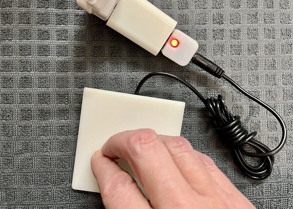
If you want to ensure that your assistive switch is functioning properly, utilize the USB Switch Tester by simply powering it with a standard USB outlet and plugging an assistive switch in.
 Electronics
 Custom PCB
 3D Printing
 1
1 9
9 0
0 618
618Device Information
Overview
The USB Switch Tester is a device used to test the functionality of an assistive switch with a 3.5 mm connection. This device allows the user to determine if their assistive switch is working. This device is not able to be used as a switch interface but rather lights up the red LED light if the switch is pressed and functional. The device is able to be plugged into a powered USB port to be conveniently used without the need for batteries. This is an alternative to the battery power Simple Switch Tester.
How To Use
The USB Switch Tester is a simple tool used to check whether an assistive switch is functioning correctly. When a working switch is connected and pressed, the tester provides clear visual feedback using a red indicator light.
Powering the USB Switch Tester
The USB Switch Tester requires power to operate.
Insert the USB-A plug into a powered USB-A port, such as:
- a computer,
- a USB battery pack, or
- a USB wall power adapter.
Once powered, the device is ready to use.
Testing an Assistive Switch
- Insert the assistive switch’s 3.5 mm plug into the 3.5 mm jack on the USB Switch Tester.
- Press and release the assistive switch.
- Observe the red indicator light:
- Light turns on when the switch is pressed and turns off when released:
- The assistive switch is working correctly.
- Light does not turn on when the switch is pressed:
- The switch may be damaged, improperly wired, or incompatible.
- Light remains on all the time, even when the switch is not pressed:
- The switch may be stuck closed or shorted.
Disability Type Description
This device is suitable for makers and assistive switch users who want to check whether a switch is working correctly.
Estimated Cost (CAD)
Maker Information
Skills Description
This is a intermediate level build that involves ordering a custom PCB, 3D printing an enclosure, and soldering thru-hole components to a PCB.
Print Time (hrs)
0.5
Assembly Time (hrs)
1
Tools Needed
3D Printer;Soldering Iron
Build Instructions
This build involves soldering thru-hole components to a custom printed circuit board (PCB), and assembling the populated PCB into a 3D printed enclosure.
Detailed step-by-step instructions with photos are available at the Project Link.
Project Link
Please login or register to agree to the MMC Terms of Use to access the Project Link
License
Attribution
Design and documentation by Neil Squire Society / Makers Making Change.
Contributors:
- Milad Haji Hassan
- Derrick Andrews
- Jake McIvor
Reviews

There are no reviews for this device